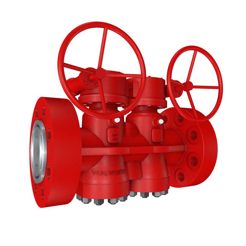
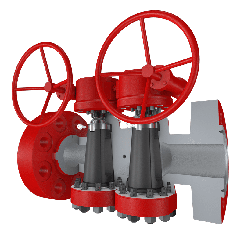
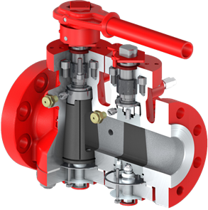
INVERTED PLUG DUAL STEEL VALVE (Bottom Entry Dual Plug Valve).
- Flow divider valve mainly used in the oil, gas and derivatives industry when double isolation is required to ensure tightness downstream of systems such as alternate injection of water and gas, skids for transferring crude oil from one customer to another (LACTS), systems with diversified bypass, where it is required to isolate compressors; It is also ideal in applications where it is required to install two valves as it saves space or where a single block valve and a blocking plate are installed.
- Design in accordance with API-6D and ISO-14313.
- Walworth twin steel plug valve design known as Compensator removes the issue of the plug snapping into the body taper when there is no sealant due to it being installed in an inverted position; therefore, gravity will pull the plug away from the taper.
- ASME Classes 150, 300, 600, 900, 1500 and 2500.
- It is manufactured with a handwheel or gear actuator oriented at the top of the valve; for handwheel of gear actuator oriented 180° to each other for ease of operation.